
Innovative 3D Printing Software
Superfast accurate Additive Manufacturing
Transform your 3D printing workflow with a Software designed for speed, quality, and automation. Import native CAD files, repair and optimize models, nest parts intelligently, and export production-ready files for all major additive technologies as accurate as defined in the CAD data.
- CAD interoperability and high precision build preparation for Catia, Nx, Solidwoirks, Creo, Inventor, STEP and JT as well as tesselated STL, OBJ and 3MF formats
- Easy repair and automatic correction of CAD and STL data
- Multiprocessor high density 3D Nesting with heat optimization
- Easy to use best in class Texture and Lattice functions
- Exact engineering quality based on CAD geometry for optimal accuracy
- Part and manufacturing analysis
- Production-ready export to 3MF, STL, and all major slicing formats
- Plugins for seamless direct Printer connection
Accelerate your path from CAD to print with superior part quality, reduced manufacturing costs, and a seamless end-to-end additive manufacturing workflow—all in one software platform

Outpace Your Competition
4D_Additive combines lightning-fast performance and the ability to process also exact CAD geometry troughout the build process. Numerous integrated functions make 4D_Additive the ultimate one-stop-shop solution for additive manufacturing.
Featuring our unique Build History Tree, the intuitive user interface sets a new benchmark for usability. Every step of the build preparation process is directly accessible and editable at any time, allowing users to review and modify all parameters throughout every step of the workflow. The result is reduced preparation time, complete process transparency and maximum control.

One Solution for all
By combining all essential tools in a single application, 4D_Additive provides maximum flexibility and ensures a seamless workflow for all 3D-Printing Technologies without the need to switch between multiple software packages.
The Healing of STL data is superfast, accurate, fully automated and can be applied on an unlimited number parts and in one go to seamlessly start the powerful nesting for all AM technologies.
High-Performance Nesting
The AI-powered 2D and 3D Nesting ensures a super fast and automated build preparation with optimal build volume utilization across all machine types. Multiprocessing enables exceptional speed and accuracy while maximizing automation. Extensive user-defined nesting options and part-specific settings provide the flexibility needed even for the most demanding applications.
The heat-optimized Nesting evenly distributes parts in order to avoid heat concentration and significantly enhances part quality. Advanced features including predefined nesting strategies for maximum build density, automated part marking, and intelligent automatic distance controle based on part thickness make 4D_Additive one of the most powerful 3D printing software solutions available today.

NECO the expertise for additive and subtractive manufacturing
“NECO is pleased to use 4D Additive Manufacturing pre-processing software for its unique texturing module, lattice tools, and nesting.”
States Robert Collier, President of National Equipment Corporation
3D Textures made easy
The innovative Texture Module creates advanced surface designs on CAD and STL models with just a few clicks. In addition to user-defined logos and patterns, the Substance Plugin provides access to thousands of parametric textures, including VDI 3400 surface finishes for aesthetic and functional applications.
Simply select the desired area and apply a texture from the database. Size, position, resolution, and depth can be adjusted visually using a photorealistic preview.
Distortion-free texture projection and real-time visualization enable the fast evaluation and creation of innovative product designs while eliminating stair-stepping and enhancing the look and feel of printed parts.


Precise Manufacturing
4D_Additive also works directly with original, precise CAD models in all major native and standard formats, preserving maximum accuracy and eliminating the inaccuracies introduced by tessellated STL or 3MF data.
Certified according to VDA 4955/2 the integrated healing technology and intuitive repair tools automatically fix gaps, overlaps, twisted faces, and other geometry defects within seconds. The result is faster data preparation and superior part quality that meets CAD Enginnering standards.
Direct modelling functions can be used to change hole diameters, wall thicknesses or to create offset areas. The corrected and adapted models can also be exported as STEP to be used in CAD workflows.
Printability Analysis
Prevent costly production errors before printing. The integrated Thickness Checker identifies areas that are too thin for the selected printing technology. In addition, the tool also analyzes clearances like holes, gaps, and others fine details that are too small to be manufactured reliably.
The checker also identifies massive zones areas where material and therefore heat accumulation occurs during printing. To reduce thermal distortion and improve surface quality, these regions can be hollowed using the hollowing and lattice generation functions.


Smart Database
The Printer Database contains more than 250 predefined 3D printing systems covering all major additive manufacturing technologies, including SLS, SLM, MJF, SLA, and FDM.
Users can easily extend the database with custom machines and process parameters tailored to their production environment, supporting both rectangular and circular build platforms.
Store your custom process parameters as customized machine profiles to streamline build preparation, save valuable build time, and prevent costly production errors.
Optimized Part Orientation
A unique real-time analysis function visualizes the expected surface quality while rotating the model manually, enabling users to find the optimal part orientation within seconds.
The Multi-Criteria Positioning automatically determines the best orientation based on the selected machine type and objectives, such as surface quality and accuracy of critical areas, minimizing support structures, or lowering the production time.
This real time analysis and automation accelerates build preparation and helps users to achieve optimal printing results.


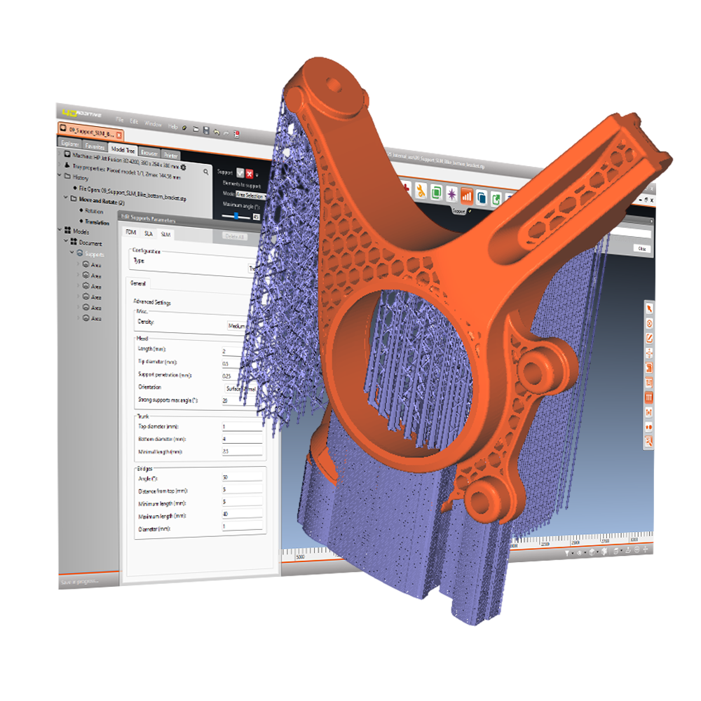
Intelligent Support Structures
4D_Additive generates supports tailored for SLA, FDM, as well as SLM metal printing. Support regions are identified automatically based on surface angles, ensuring reliable support placement with minimal user interaction. Supports can be created automatically or individually by selecting the predefined areas.
The innovative tree supports minimize contact with the part, reducing post-processing effort and improving surface quality on down-facing surfaces. Their branched design also reduces the contact area on the build platform, lowering material consumption and simplifying support removal.
For maximum flexibility, users can easily add, modify, or remove contact points and tree branches to customize the automatically generated support structures according to specific requirements.
Advanced Cutting Functions
Parts that exceed the build volume of a printer can be split easily using a variety of 2D and 3D cutting methods. Supported options include polyline and puzzle cuts, as well as intelligent joining features such as pins and lap joints for precise reassembly after printing.
Custom cutting profiles can be defined and reused to automate repetitive tasks and streamline the workflow. The resulting parts can be exported as STL or STEP files, enabling seamless integration into manufacturing and CAD processes.


Hollow and Lattice Structures
4D_Additive provides powerful and easy-to-use hollowing tools to reduce part weight, material consumption, as well as heat input while maintaining a user-defined wall thickness. Solid models can be hollowed, filled with lattice structures, or areas of the model can be replaced by external lattice geometries, while preserving functional areas as original CAD geometry.
More than 23 lattice types are available, including Honeycomb, Octet, Gyroid, Voronoi, and BASF presets. Through the Forward AM partnership, the Ultrasim® 3D Lattice Library combines lattice designs with material, machine, and process data for FFF, MJF, and SLS applications. Create lightweight components, foam replacements, cushioning solutions, and functional prototypes in seconds with just a single click.
Production-Ready Slicing
4D_Additive has a powerful and proven slicer for all additive manufacturing technologies, as well as a complete build manager for FDM, SLS, and SLM applications. Thanks to multiprocessor calculation, even large and complex build jobs are processed at exceptional speed. The slicer supports triagulated as well as CAD models.
STL and the optional exact B-Rep slicing creates precise spline curves for laser controllers and FDM machines, with output options including SVG and G-code. For SLA and DLP systems, a high-resolution PNG image generation supports up to 8K.
The integrated HP Plugin printer connection enables up to 20 jobs simultaneously with no file size limitations. 4D_Additive also supports a wide range of slicing formats like amf, 3mf and STL as well as in common slicing formats cli, sli, abf, svg, sls, usf and g-code. In edition tailored formats for WLS (WLS), EOS (SLI and CLI), Voxeljet (VXJ), and SLM (SLM) machines guarantee a seamless build job transfer for all major printers and additive manufacturing technologies.

You are currently viewing a placeholder content from YouTube. To access the actual content, click the button below. Please note that doing so will share data with third-party providers.
More Information